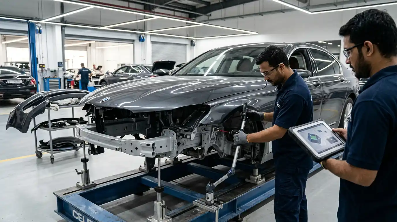
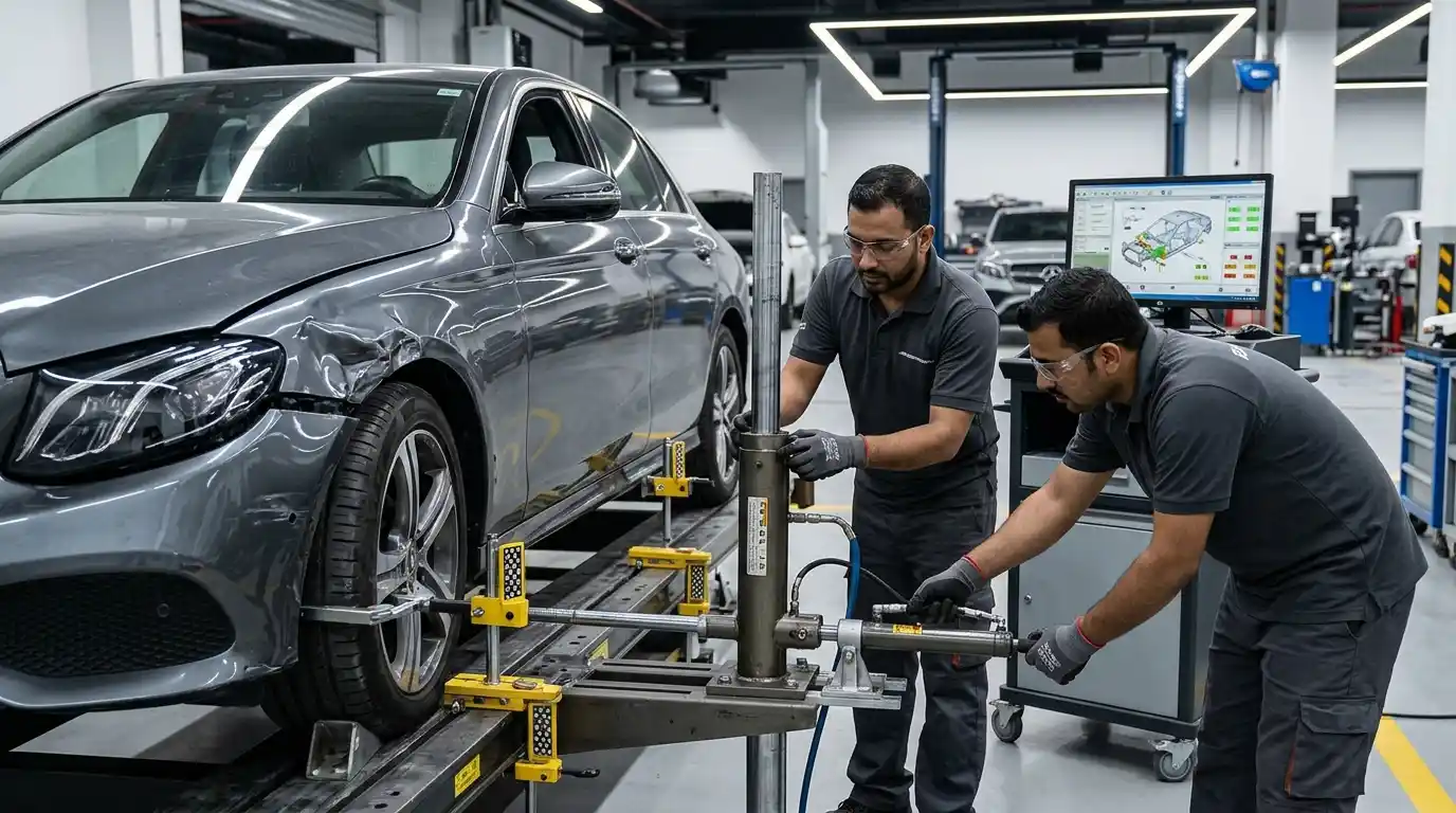
Measure, anchor, pull, remeasure
Car Frame Straightening Dubai
Frame straightening is a controlled geometry correction, not a promise to pull every bent part. The vehicle must be measured, secured and repaired within the allowed limits for its construction and materials.
Bodyshop.ae separates correctable distortion from components that must be replaced, then records the measurement path before, during and after correction.
Closed-loop correction
Every pull must answer a measurement
Frame straightening is one operation within broader accident repair service in Dubai. The loop protects against cosmetic alignment that leaves hidden reference points out of position.
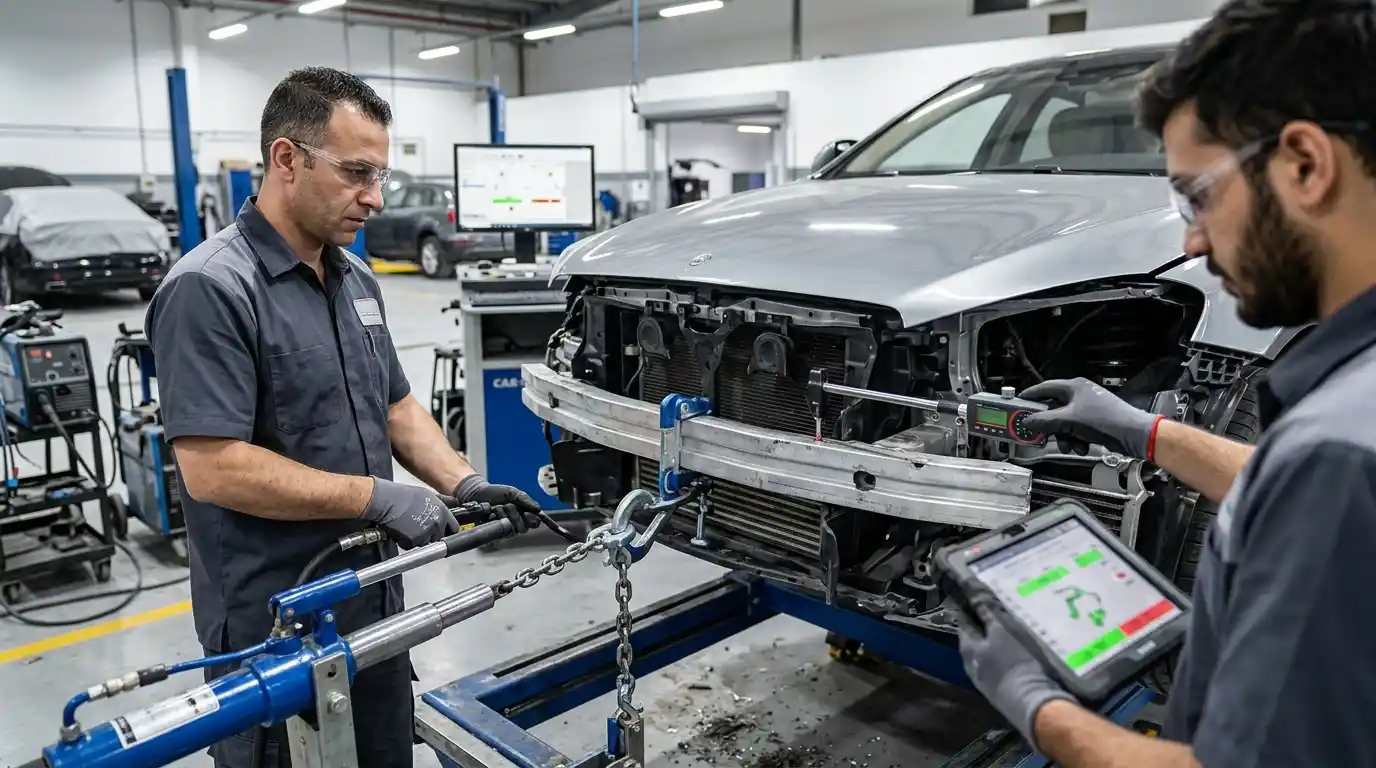
-
Baseline
Measure the vehicle as received
Compare accessible length, width and height reference points with suitable data. Record blocked points and suspected suspension movement.
-
Setup
Support and anchor correctly
Place the vehicle on an appropriate bench or system, support its weight and secure approved anchoring points without creating new damage.
-
Strategy
Plan the force path
Identify the impact direction, repairable parts, replacement parts, pull sequence, attachment protection and points that must be monitored.
-
Correction
Apply controlled force
Use gradual pulls in the required vector. Avoid uncontrolled force, heat or attachment methods that conflict with vehicle information.
-
Feedback
Measure during the pull
Watch target and surrounding points for movement, springback and unintended transfer. Stop when readings or material response challenge the plan.
-
Replacement
Join approved components
Complete replacement at supported locations using specified cutting, fitting, welding, riveting, bonding and protection operations.
-
Final geometry
Repeat the measurement
Verify relevant points after release or as required, not only while pulling force holds the vehicle in position.
-
System check
Reconnect the whole vehicle
Confirm closures, subframes, suspension, alignment, scans, restraints and ADAS requirements before handover.
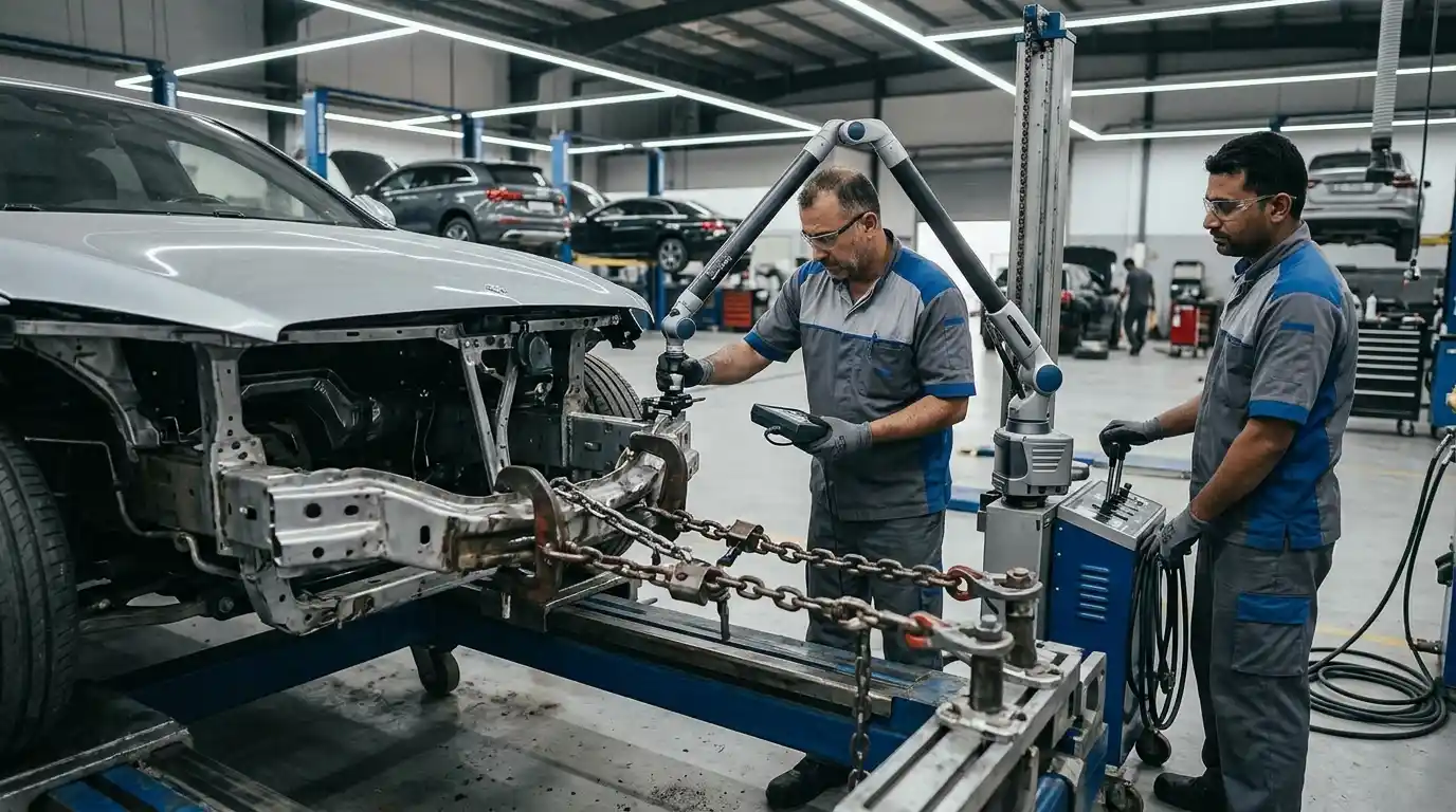
A pulling tower creates force. The measuring system decides whether that force is producing the intended geometry.
One corrected point does not guarantee that the neighbouring rail, crossmember, pillar, floor or mounting point followed correctly.
Measurements should remain connected to the impact map and vehicle-specific repair information.
Bench setup decisions
The setup must suit the vehicle and the operation
Bench, rack, jig and electronic measuring systems perform different jobs. The repair plan states how the vehicle is supported, fixed, measured and loaded.
| Equipment or input | Primary job | Important limitation |
|---|---|---|
| Structural bench or rack | Supports the vehicle and provides reaction for controlled pulling | Does not supply the correct repair points or material permissions by itself |
| Anchoring and fixtures | Hold approved areas so applied force can be controlled | Incorrect attachment can damage sills, pinch welds, frame points or EV protection |
| Pulling tower and force hardware | Apply force in a planned direction | More force is not a substitute for the correct vector, sequence or repairability decision |
| Three-dimensional measuring | Tracks point position in length, width and height | Needs reliable vehicle data, point access and correct setup |
| Body jig or model fixture | Locates or supports specified points during correction or replacement | Availability and required use are vehicle and procedure specific |
| Wheel alignment equipment | Measures wheel geometry after relevant repair | Cannot replace main-body structural measurement |
| Scan and calibration tools | Support system diagnosis and specified post-repair operations | Cannot prove the metal structure is straight |
Bench correction detail
Anchoring and pull sequence determine what the machine can control
A frame bench is a holding and measuring platform, not proof that every displaced part should be pulled. The vehicle is secured at suitable points so corrective force can be applied without allowing the body to move on the bench. Anchoring depends on the construction, damage location and equipment; weak, corroded or already damaged points cannot be used as reliable restraints.
The pull plan follows the collision load path. Several gradual, measured pulls may control movement better than one large pull. Force applied at the wrong height or angle can twist a rail, close an opening or transfer distortion into an undamaged area. The technician monitors surrounding points, springback and locked stress as connected parts are relaxed.
Three-dimensional measurement tracks length, width and height from defined datum references. Centreline points, diagonals, suspension locations, powertrain mounts and body openings are checked against suitable vehicle data. Initial readings establish the condition, in-process readings guide correction, and final readings verify the released geometry. A visually straight rail is not a measurement report.
Straightening stops when the material or damage no longer supports correction. A smooth bend in an approved area differs from a sharp kink, tear, cracked weld, stretched flange or damaged ultra-high-strength reinforcement. Heat is not a general shortcut; OEM repair information must define any permitted method, replacement boundary and joining requirement.
Panel gaps and closures are checked before permanent joining so replacement parts are not forced onto incorrect geometry. Wheel alignment may identify suspension-reference concerns, but adjustment must not conceal structural displacement. Calibration follows only after geometry, ride height and alignment prerequisites are correct.
The estimate should list measuring, setup, controlled correction, replacement, joining, corrosion protection, alignment and calibration separately. Hidden damage found after authorised access should be added through a documented supplement rather than buried inside one frame-machine charge.

Cold straightening has boundaries
Material strength decides whether pulling is allowed
Modern structures combine different steel grades, aluminium forms and mixed-material joints in precise locations. A crease that looks repairable may still require replacement when straightening would alter its strength, heat treatment or crash function.
Strength grade controls the repair route
Honda’s June 2026 high-strength-steel guidance, reproduced through I-CAR’s OEM technical resource, calls for body dimensions to be monitored during gradual pulls and requires replacement above its stated damage threshold. That threshold is a Honda example, not a universal rule.
Heat is not a general straightening shortcut
Unapproved heating can change high-strength steel beyond the visible hot spot. Permission, temperature, method and any affected replacement area must come from the exact vehicle repair information.
Sheet, casting and extrusion behave differently
One aluminium component may support controlled correction while another requires replacement. Alloy form, clean tooling, isolation and the specified joining technology all affect the decision.
Replacement can be the correct structural route
The broader collision frame repair guide explains repair-versus-replacement planning. Frame straightening should not be presented as automatically cheaper when replacement is the supported method.
Ask for numbers before agreeing to a pull
Request the initial measurement and repairability review
Send the impact direction, wheel and closure relationships, underbody damage, warnings and any prior alignment report. Inspection can then define accessible reference points, required setup and parts that may not be straightened.
Pulling errors leave patterns
Poor correction can move the problem instead of solving it
Closures are adjusted before structure
Hinges, latches and bolt-on panels can be moved to hide a dimension problem. The gaps may return or transfer misfit to another opening.
One datum is corrected in isolation
The target point reaches specification while adjacent height, width or diagonal relationships remain wrong. A network of points must be watched.
Force passes the intended position
Some controlled overpull can account for springback where supported, but guessing can stretch metal or distort neighbouring zones.
Material is softened to move faster
Unapproved heat can compromise strength and expand the affected replacement scope even when the panel later looks straight.
The vehicle moves on the bench
Uncontrolled setup changes the force path and measurement reference. It can also create fresh sill or frame-point damage.
Final numbers are taken under force
The structure can spring back after chains or fixtures are released. The final verification follows the specified unloaded or supported condition.
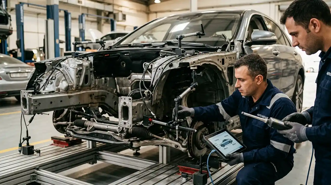
Read the measurement network
Length, width and height tell different parts of the story
Length measurements can reveal mash or setback along a rail or frame member. Width can reveal sway, side movement or an opening that has narrowed. Height can reveal sag, buckle or a mounting point that has moved vertically. Diagonal relationships help show whether a rectangular opening or reference network has become diamond-shaped.
The repair plan does not rely on one convenient point. It compares centreline, paired and diagonal points around the affected zone and includes unaffected reference areas when useful. A point can appear correct in plan view while remaining wrong in height, so two-dimensional tape measurements are not enough for complex damage.
Bolt-on panels are removed or adjusted only after their relationship to the structure is understood. A wing, bonnet, door or bumper can create misleading gaps through damaged hinges, brackets or attachments. Conversely, adjusting a bolt-on panel can temporarily hide movement below it.
Body-on-frame vehicles add body mounts and the relationship between upper body and separate frame. Unibody vehicles integrate rails, sills, floors, pillars and crossmembers. The equipment and data must match the actual construction rather than the everyday word frame.
Initial readings set the baseline, in-process readings guide force and final readings verify the released structure. The invoice should identify which of those records are supplied and which points could not be accessed.
Proof-of-work record
A frame-straightening handover needs more than panel gaps
Before correction
- Impact and gap photographs retained
- Initial three-dimensional readings recorded
- Reference data identified
- Repairable and replacement parts separated
During correction
- Anchoring and support points documented
- Pull sequence follows the repair plan
- Relevant points monitored during force
- Material and heat limits respected
After correction
- Final structural readings recorded
- Measurements confirmed in the required condition
- Closures and mounting points verified
- Corrosion protection restored
Whole-vehicle checks
- Subframes and suspension inspected
- Wheel alignment result retained
- Relevant post-scan completed
- Calibration and restraint status documented
Frame correction questions
Car frame straightening questions
How do technicians know where the frame is bent?
They combine impact evidence, body and underbody inspection, closure and wheel relationships, and three-dimensional reference-point measurements compared with suitable vehicle data.
Can every bent frame part be pulled straight?
No. Material grade, component design, deformation, tears, kinks, heat history and vehicle-maker procedures can require replacement rather than straightening.
Is frame straightening only for body-on-frame vehicles?
No. The search term is also used for controlled structural correction on unibody vehicles, although the actual parts may be rails, sills, floors, pillars or other integrated structure.
Does the vehicle need wheel alignment afterwards?
Often alignment is relevant after structural or suspension-related work, but the exact need depends on the repair. Alignment complements structural measurement and does not replace it.
Can frame dimensions be checked without dismantling?
Some points may be accessible, while others are blocked by covers, suspension, trim or damaged parts. The estimate should state which measurements are preliminary and which need authorised access.
Will the car drive exactly as before?
The repair objective is to restore supported geometry and affected systems within the approved process. Final handling also depends on wheels, tyres, suspension, steering, alignment and pre-existing conditions, all of which must be checked separately.
End with the measurement
Keep the initial and final records together
The accident repair cost guide can help compare whether structural setup, measuring and alignment are included in a wider estimate.
The clearest frame-straightening result is a traceable path from the original deviation to the final verified geometry, with every replacement and system check attached. If that path is missing, a straight reflection is not enough.
Keep the initial report even when later readings fall within the required position. It shows the direction and scale of movement and helps explain why suspension, alignment, closure or calibration checks were carried forward.
Ask whether readings were taken before anchoring, during force and after release. A result printed only while the vehicle is held by chains or fixtures can conceal springback. The final state must reflect the condition required by the measuring and repair process.
Where a point remains inaccessible, the limitation should be named with the reason and next action. Do not replace a missing measurement with a general statement that the vehicle looks straight.
Retain the part and operation list beside the measurement report. Geometry can return to specification through straightening, replacement or a combination, and the record should show which route restored each affected zone.