
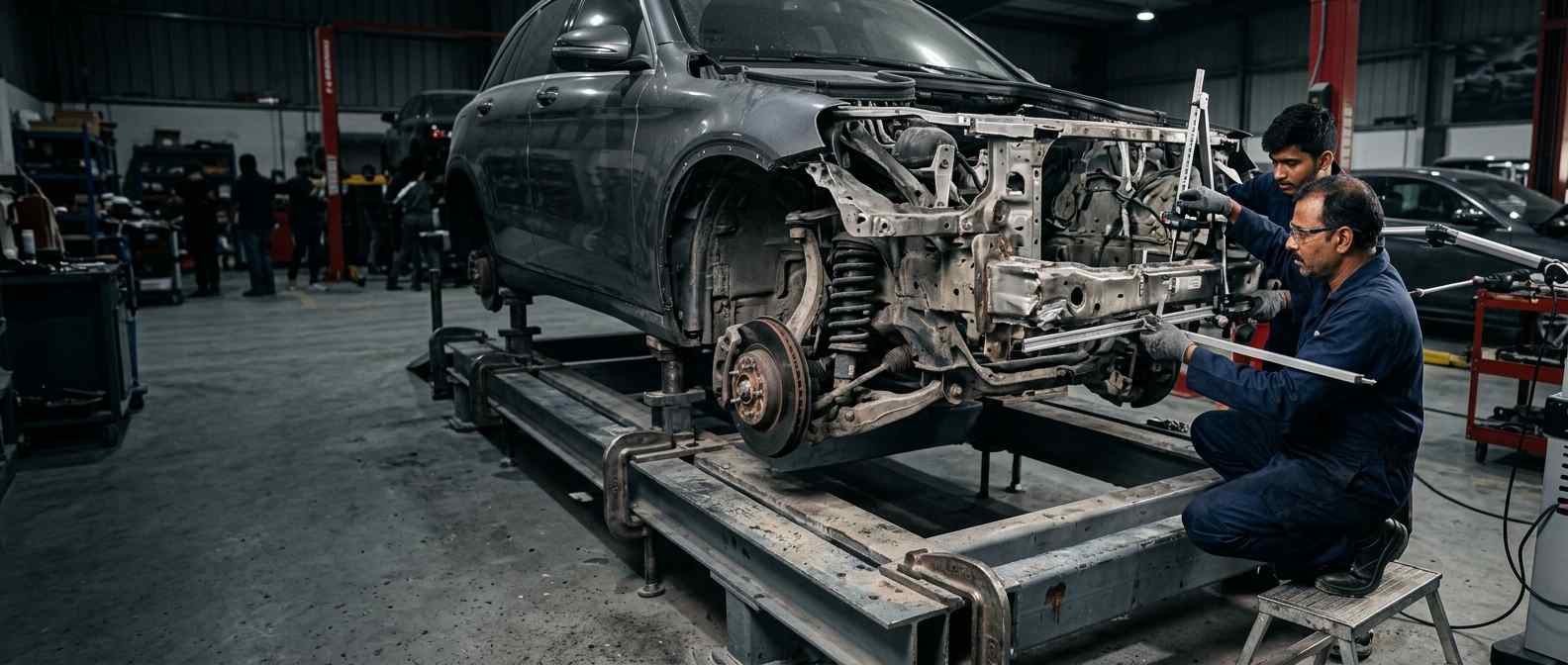
Structure first, visible panels second
Car Chassis Repair Dubai
Car chassis repair starts by naming the damaged structure. A front rail end, outer sill, floor, pillar, crossmember, bolt-on subframe and separate ladder frame are not the same component and do not share one repair method.
Bodyshop.ae inspects the impact path, measures relevant reference points and separates repairable distortion from components that require replacement under vehicle-specific information.
Safety action before diagnosis
Stop driving when the impact may affect control or containment
Do not drive merely to test whether a collision-damaged vehicle pulls or vibrates. Arrange inspection or recovery when a wheel has moved, a tyre rubs, steering or braking has changed, fluid leaks, an airbag has deployed, a door or bonnet will not latch, the floor is crushed, high-voltage damage is possible or a safety warning remains.
A photograph cannot declare the vehicle safe. Visible panel gaps and wheel position can help triage, but structure, suspension, steering, cooling, restraints and battery protection may hide behind apparently minor outer damage.
The correct starting route is the accident repair service in Dubai when the impact crosses several systems. Cosmetic car body repair service remains appropriate for local outer damage only after wider risk has been excluded.
Do not attempt DIY pulling, welding, heating or structural hammering. Modern steels, aluminium castings, extrusions, adhesives, rivets and joining zones have repair limits that cannot be identified reliably by appearance.

Chassis is a broad search word
Name the construction before describing the repair

Integrated body structure
Rails, aprons, pillars, roof rails, sills, floors and crossmembers work as a connected body. Damage can travel beyond the visibly crushed panel.
Body mounted to a separate frame
The ladder or perimeter frame, body mounts and upper body require related but separate checks. A straight-looking body does not prove frame geometry.
Bolt-on suspension or powertrain carrier
A front or rear subframe can bend or shift while the main body remains within specification, or it can hide damaged mounting points above it.
Reinforcements and crush zones
Bumper beams, crash boxes and rail ends manage energy through designed deformation. Replacement and attachment procedures are vehicle specific.
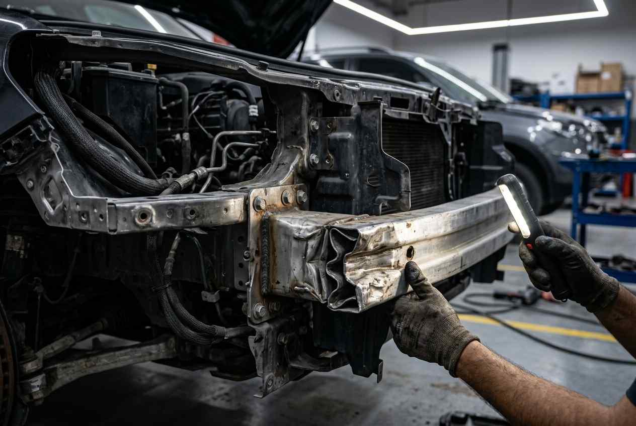
Diagnosis before force
Each evidence layer answers a different question
Alignment alone cannot prove the structure is correct, and panel gaps alone cannot prove it is wrong.
| Evidence | What it can reveal | What it cannot prove alone |
|---|---|---|
| Impact and gap map | Direction of load, closures, creases, displaced panels and likely transfer path | Exact hidden dimensions or material repairability |
| Underbody inspection | Rails, floors, seams, mounts, scrapes, crushed points and leakage | Three-dimensional geometry without measurement |
| Diagnostic scan | Faults in restraints, chassis, steering, sensors and other modules | Physical straightness or absence of mechanical damage |
| Wheel and suspension check | Wheel setback, damaged arms, hubs, tyres, subframes and steering relationships | Main body dimensions unless reference points are measured |
| Structural measurement | Differences between actual reference points and suitable vehicle data | Whether a material can be pulled, heated, sectioned or repaired |
| Material and procedure review | Allowed straightening, sectioning, replacement and joining operations | Current vehicle condition without physical inspection |
| Controlled access | Hidden reinforcements, reverse-side deformation, cracked seams and damaged attachments | Final cost before all affected systems and parts are confirmed |
Do not authorise a bumper-only estimate for a deeper impact
Ask for the impact path and measurement plan
Send the full vehicle position, every affected corner, wheel relationships, closure gaps, underbody contact, warnings and accident report details. The first estimate should state what is visible, what must be measured and what remains conditional.
Structural repair pathway
Measurement follows access and guides the repair decision
The exact order changes with damage, but repair and replacement must remain connected to evidence.
-
Stage 01
Record and isolate
Photograph the complete vehicle, impact zones, wheels, gaps, warnings and existing damage. Apply EV or restraint precautions where required.
-
Stage 02
Map the load path
Follow deformation from bumper or outer panel towards rails, aprons, sills, pillars, floors, crossmembers and mounts.
-
Stage 03
Scan relevant systems
Preserve collision-related faults and identify restraint, chassis, steering, ADAS or powertrain information needed for the repair plan.
-
Stage 04
Gain controlled access
Remove only authorised components needed to inspect reinforcements, seams, reverse sides and reference points without destroying evidence.
-
Stage 05
Measure actual geometry
Compare accessible three-dimensional points with suitable vehicle data. Record initial deviations and blocked points.
-
Stage 06
Review material limits
Identify steel grade, aluminium, casting, extrusion, composite, adhesive and joining requirements using current vehicle information.
-
Stage 07
Choose repair or replacement
Approve pulls only where allowed. Replace components that exceed repair limits or have no supported procedure.
-
Stage 08
Correct and join
Measure during controlled correction, use the specified section or factory seam, reproduce approved joints and protect adjoining systems.
-
Stage 09
Restore protection
Reapply primer, seam sealer, cavity wax, underbody protection and coatings in disturbed areas according to the repair plan.
-
Stage 10
Verify the assembled vehicle
Repeat measurements, check suspension and alignment, complete scans or calibration, verify closures and document the result.
Structural repairability
Material, load path and damage location control the repair method
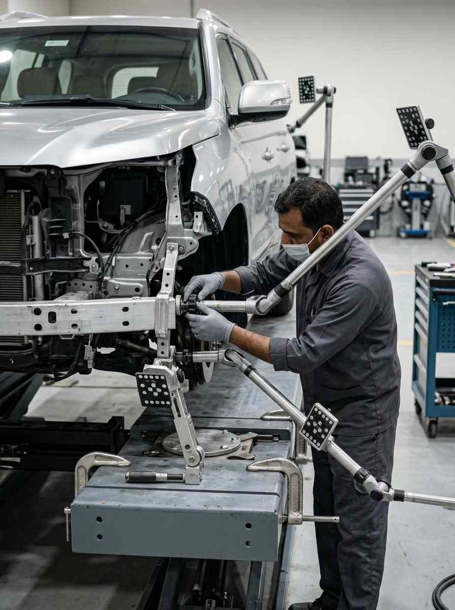
Modern body structures combine mild steel, high-strength steel, ultra-high-strength steel, aluminium, castings, extrusions, composites and bonded or mechanically fastened joints. Two rails that look similar can have different material grades and permitted repair boundaries. Heat, sectioning, pulling and welding cannot be selected by appearance. Vehicle identification and current OEM repair information must control what may be repaired and what must be replaced.
A unibody carries loads through rails, aprons, sills, pillars, floors, crossmembers and reinforced joints rather than through one separate chassis frame. A body-on-frame vehicle adds a ladder frame and body mounts, but suspension and powertrain references still matter. The damage map follows the impact path across visible and hidden connections so the estimate does not treat one buckled end as an isolated cosmetic problem.
Three-dimensional measurement compares centreline, height and length references with reliable vehicle data. Datum points, suspension mounts, powertrain mounts, openings and diagonals help locate displacement. One correct point does not prove the complete structure is correct. Initial measurements define the repair plan, in-process measurements guide correction, and final measurements document the achieved geometry within the applicable tolerances.
Pulling is used only where the structure and repair method allow controlled correction. Anchoring, pull direction and sequence are planned to reverse the damage path while protecting undamaged sections. Kinks, tears, cracked coatings, elongated holes and work-hardened areas can limit repairability. A part that returns to a nominal dimension may still require replacement if its material properties or joining area have been compromised.
Replacement work includes more than cutting and welding. The procedure can specify sectioning location, joint preparation, weld type and number, adhesive, rivets, fasteners, fit checks and corrosion protection. Weld-through primer, seam sealer, cavity wax and exterior underbody protection have different functions. Restoring visible shape without restoring the joint and protective layers leaves an incomplete structural repair.
Final verification connects structure with the rest of the vehicle. Panel openings, door operation, glass fit, suspension geometry, steering, wheel alignment, subframe position and ADAS prerequisites may depend on the corrected body. The repair file should retain before-and-after measurements, authorised changes, joining records, corrosion-protection evidence and any required scan, alignment or calibration result.
Repairability is material specific
Heat, pulling and sectioning are not universal rights
Some distortion may support controlled cold correction
Even conventional steel needs reference measurements, access and a supported repair route. Creases, thinning, tears and attachment zones can still require replacement.
Strength grade changes what is allowed
Many high-strength and ultra-high-strength parts have strict straightening, heating and sectioning limits. The procedure and material map control the decision.
Alloy and component form matter
Sheet, casting and extrusion behave differently. Heat treatment, contamination control, dedicated tools and replacement limits may apply.
Joints can combine several technologies
Adhesive, rivets, welds, isolation layers and galvanic-corrosion controls must be reproduced at approved locations.
Damage can extend below the visible surface
Cracks, delamination and bonded attachments need material-specific inspection. Metal-style pulling or filler is not a safe substitute.
Battery enclosure and high voltage add a separate gate
Underbody impact, isolation, lifting, welding, heat and battery-area repair require vehicle-specific precautions and qualified responsibility.
Repair versus replacement record
The structural decision should name the damaged feature
Repairability is not decided by whether a dent can be pulled until it looks smooth. The planner records sharp kinks, tears, holes, crushed flanges, separated joints, buckled reinforcements, stretched material and the relationship to suspension, restraint or battery mounts. Those features matter more than the surface size alone.
Replacement can mean a complete component at factory seams, an approved partial replacement or another vehicle-specific operation. Section locations, overlaps, inserts, adhesives, rivets, weld types and access holes are defined by the procedure. A convenient cut chosen in the workshop is not automatically supported.
When straightening is allowed, the estimate states the part, measured deviation, pull setup and verification. When replacement is required, it states the replacement boundary, joining method and protection to restore. Conditional language remains appropriate until dismantling exposes the reverse side and adjacent joints.
The record also distinguishes accident damage from pre-existing corrosion or repair. A new collision can open an old seam or reveal earlier filler, but the cause and approved responsibility still need evidence. Combining both into one unexplained chassis line creates cost and warranty disputes.
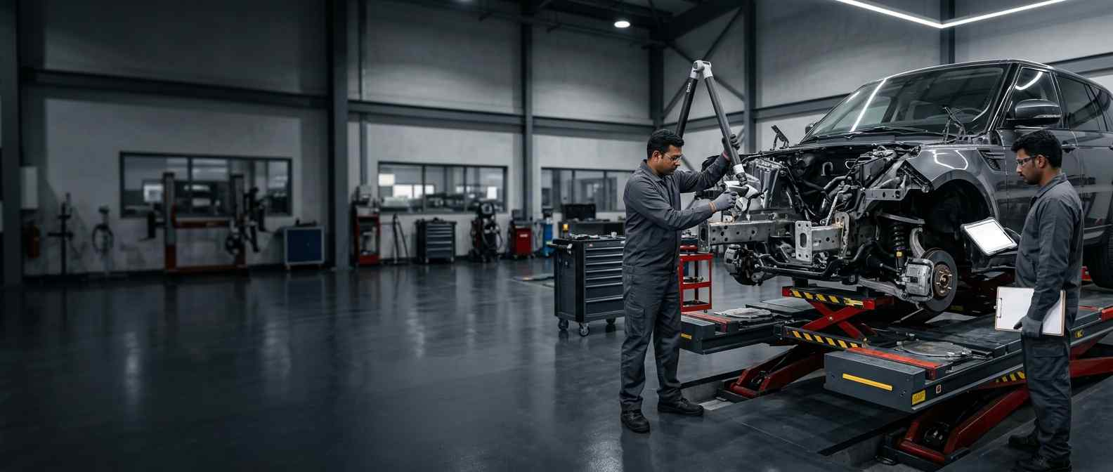
Cost is built from operations
A chassis quotation should name six separate cost drivers
Inspection and scanning establish affected systems. Controlled disassembly exposes hidden damage. Structural measurement compares actual points with data. Correction or component replacement restores geometry. Joining and corrosion protection restore the repaired area. Reassembly, alignment, diagnostics and calibration verify the complete vehicle.
Parts availability can stop the active repair even after measurement is complete. Rails, aprons, sills, pillars, floors, subframes, suspension parts, airbags, seatbelts, wiring, sensors, trims and one-time fasteners may follow different supply routes.
For structural pricing specifically, our chassis repair cost guide explains how measurement, bench setup, repairability, parts and verification shape the quotation. The accident repair cost guide provides the wider framework for comparing collision quotations. For structural work, ask whether bench setup, measuring, pulling, replacement sections, joining consumables, corrosion protection, alignment, scans and calibration are included or provisional.
Prices are indicative only when approved. The final quotation depends on inspection, vehicle construction, measurement, damage severity, material, dismantling, parts, electronics, safety systems, calibration and current availability. A photograph cannot settle those variables.
Structural handover evidence
The result needs measurements and connected system checks
Geometry
- Initial and final relevant dimensions are recorded
- Reference data source is identified
- Panel openings and closure operation are checked
- Wheel relationship and alignment results are retained
Repair execution
- Repaired and replaced structural parts are listed
- Joining locations and methods follow the approved route
- Repair limits and any remaining limitation are written
- One-time fasteners and affected mounts are addressed
Protection
- Bare metal is treated
- Seam sealer is restored where disturbed
- Cavity protection reaches repaired enclosed areas
- Underbody and anti-chip coatings are reinstated
Systems and records
- Relevant post-repair scan is completed
- Restraint and warning status is clear
- ADAS calibration responsibility is documented
- Invoice and photographs identify the structural scope
Structural repair questions
Car chassis repair questions
Can a bent car chassis always be straightened?
No. Repairability depends on the exact component, material, damage, deformation, manufacturer information and available procedure. Some parts or material grades require replacement.
Does poor wheel alignment prove chassis damage?
No. Tyres, wheels, suspension, steering, subframe position and body mounting points can all contribute. Alignment findings may justify structural measurement but do not replace it.
Can a car with chassis damage be driven to the workshop?
Do not assume it is safe. Recovery is appropriate when steering, braking, wheel position, tyres, cooling, airbags, latches, high voltage or structural security may be affected.
What is the difference between chassis repair and frame straightening?
Chassis repair is the broader structural service covering diagnosis, correction, replacement, joining and protection. Frame straightening is the controlled measurement and pulling operation used only for repairable distortion.
Will the doors and panel gaps become normal again?
Closures and gaps are useful verification points, but the expected result depends on original tolerances, hinge and latch condition, replacement parts and the full impact path. They should be checked with measurements rather than adjusted cosmetically first.
Does chassis repair require ADAS calibration?
It may when structural correction, alignment, sensor mounting or another specified event affects a fitted system. The exact OEM procedure determines the requirement.
A straight-looking bumper is not structural proof. A documented measurement and repair route is.
The collision frame repair guide explains why frame symptoms and repair options need evidence rather than visual certainty.
If measurement is blocked or repair information is unavailable, the limitation should remain visible. It is safer to stop than to invent a structural procedure.